Chapter 1: Project Introduction
In Design Talk #2, Pontech introduces an insightful topic featuring precast concrete components through a factory project the company has executed. In this project, Pontech was responsible for transforming the initial design concept into accurate shop drawings, supporting the production and erection of components on site.
-
-
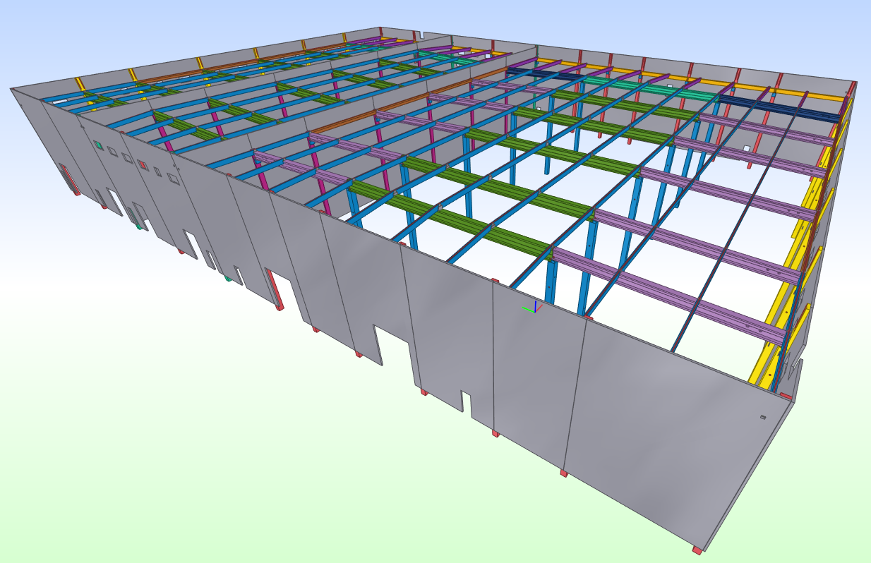
The 3D precast structural model developed by Pontech using Tekla Structures shows the complete framework of columns, beams, and walls.
-

-
Precast concrete design for the BEMACO project – Pontech’s structural solution.
To fulfill this role, Pontech applied a fully digital design process. Specifically, the company utilized Building Information Modeling (BIM) and AutoCAD as the two primary tools for this precast concrete structural project. 3D BIM software enables detailed modeling of concrete and steel structures, especially useful for precast detailing and automated drawing extraction. Meanwhile, AutoCAD is used for adjusting traditional 2D drawings, ensuring that the final documents are user-friendly for both factory and site personnel. This combination allows Pontech to leverage the strengths of both 3D models and 2D drawings, resulting in an efficient and accurate design workflow.
Chapter 2: Design Implementation of Precast Concrete Columns
2.1. Layout and Column Numbering
In the project, the design implementation of precast concrete columns began with a thorough review of the structural floor plan provided by the basic design consultant. Based on this drawing, engineers identified the position, elevation, and preliminary cross-section of each column.
To ensure effective management, a dedicated layer for the column system was created on the CAD drawing. The next step involved numbering the columns based on a consistent rule: prioritizing numbering from the center outwards, and from top to bottom. Each type of column—classified by height, type of connection, and position (interior column or edge column)—was assigned a unique code. For instance, a column with a 300×300 mm section located at the center would have a different code from an edge column of the same section that includes a console for beam support.
This process generated a complete list of column codes, serving as a database for managing both factory production and on-site erection, ensuring each component is manufactured and installed in its designed location.
-
-
The model shows a perspective view of the precast column layout. Columns are color-coded by grid line, allowing for easy inspection and management.
-
-
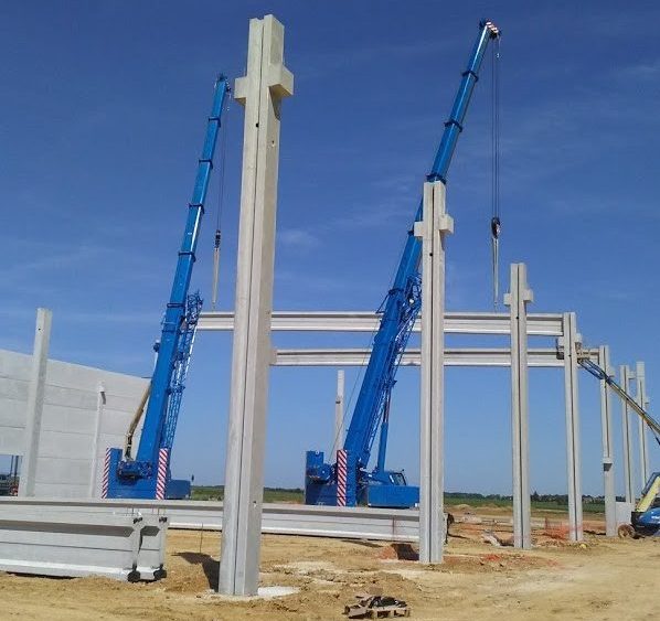
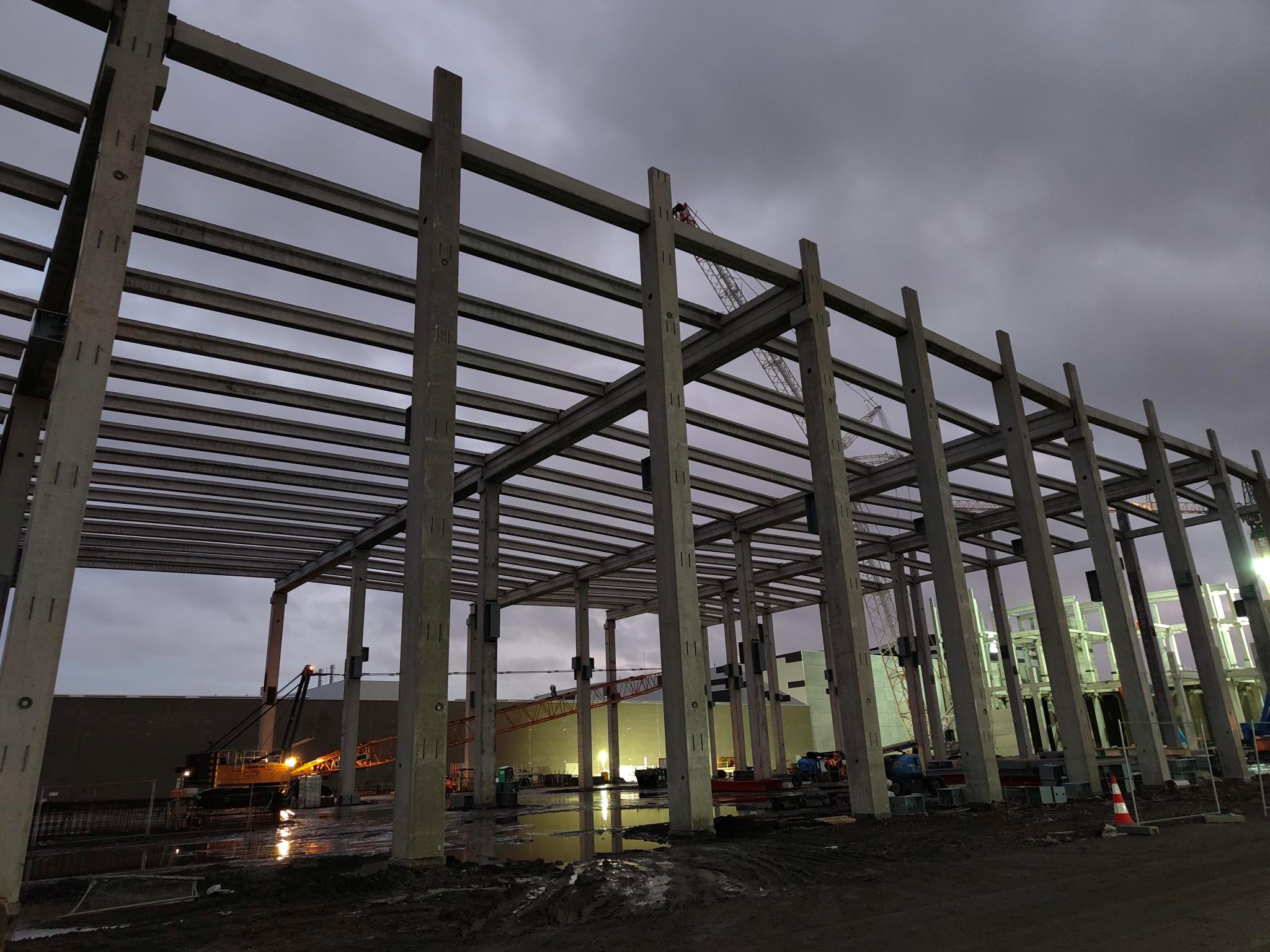
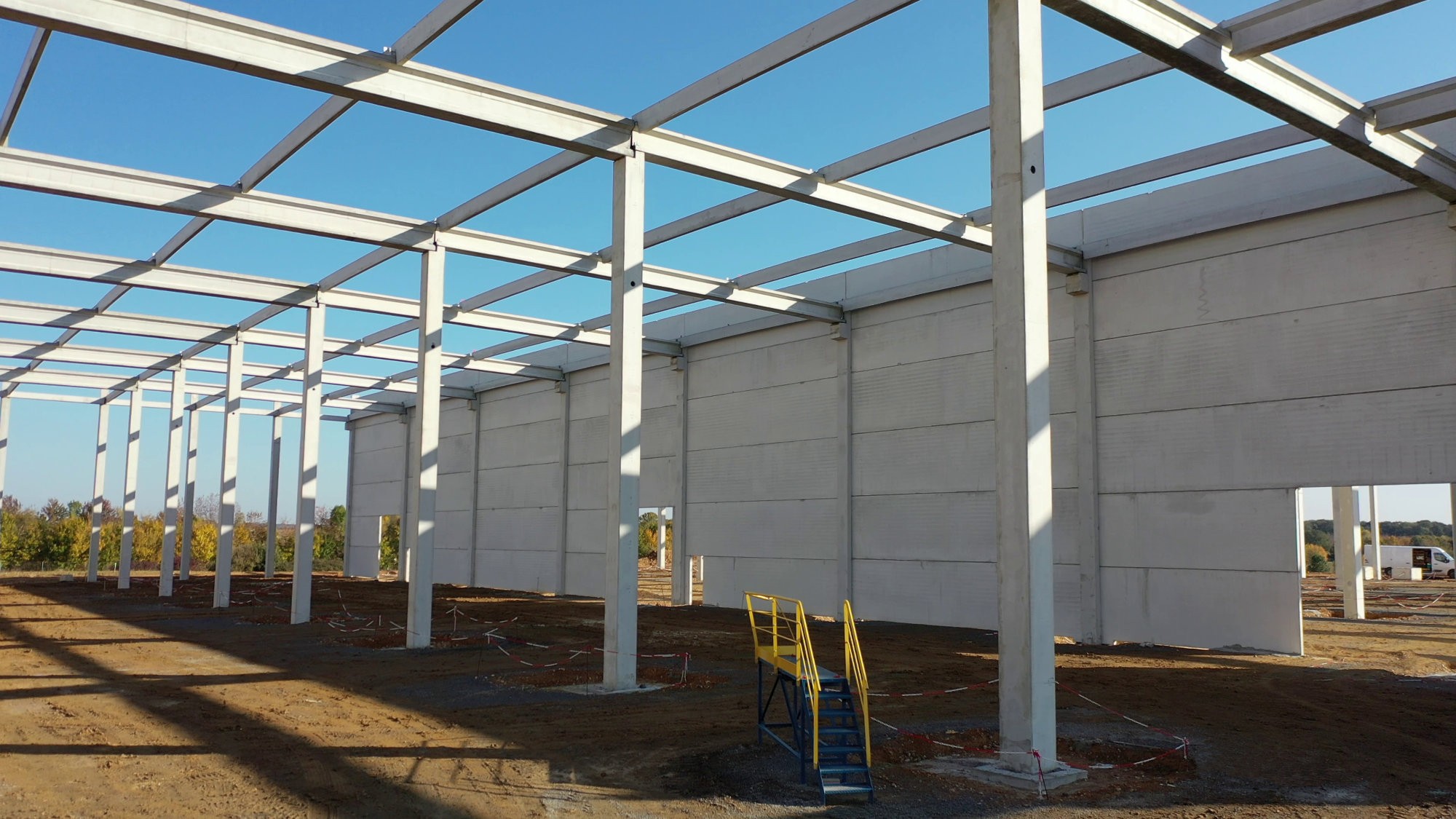
The actual site photo after erection clearly reflects the column numbering logic based on grid line – elevation – and position, corresponding precisely to the BIM model.
2.2. Column Detail Drawings (COF & ARM)
After the numbering and classification process, Pontech proceeded to develop detailed drawings for each column type. Each precast column drawing typically includes two main components: the COF drawing and the ARM drawing. These are technical terms used by Pontech:
-
COF (Coffrage): This refers to the formwork or concrete shape drawing of the column. The COF drawing illustrates the geometric shape of the column (cross-section, height, notches, embedded holes if any), as well as surface features visible after casting.
-
ARM (Armature): This is the reinforcement drawing of the column. The ARM drawing presents detailed rebar layouts, including vertical bars, stirrups, anchor hooks, starter rebars, etc., specifying the bar sizes, quantities, and spacing.
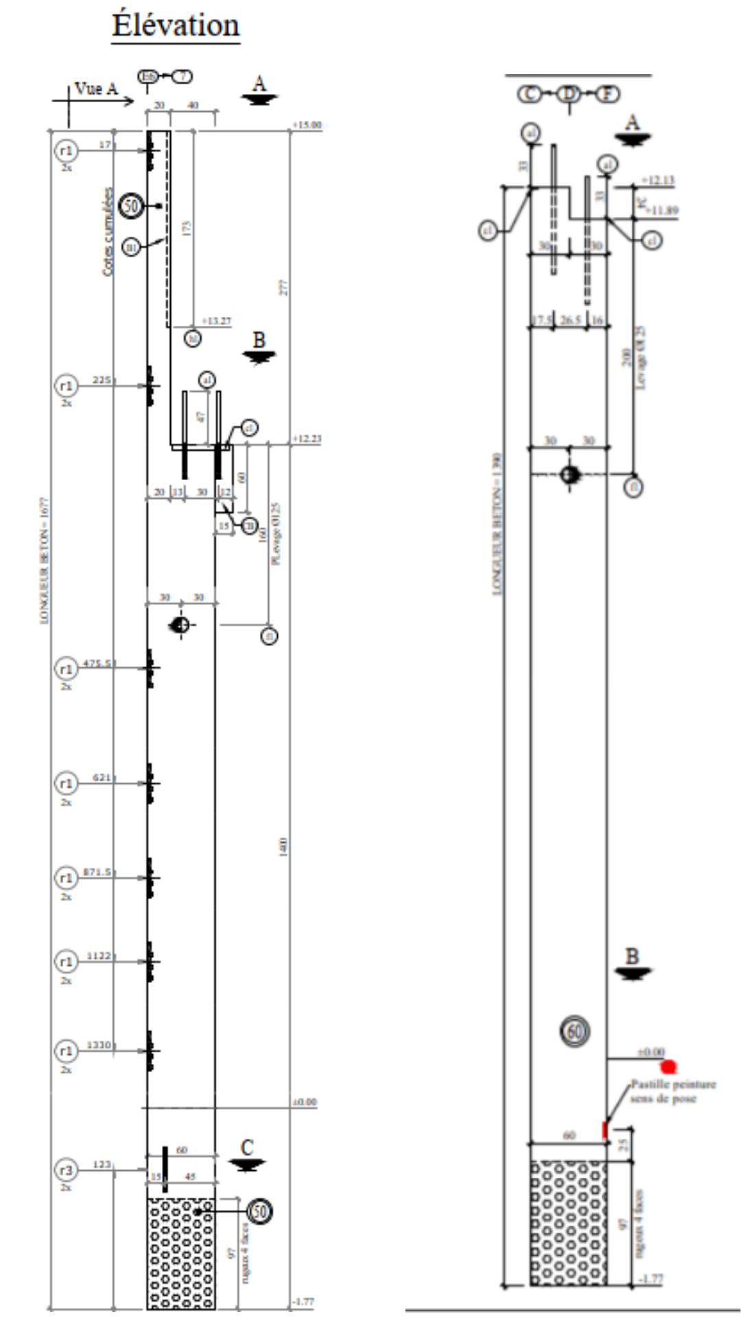
2D COF Drawings – Edge Column & Interior Column
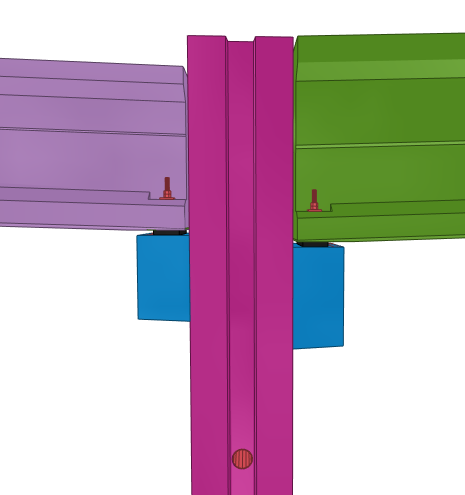
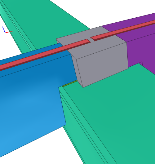
The model illustrates the connection between precast column and beam, clearly showing anchor bolts, shim plates, and required construction gaps.
The site photo shows the column installed exactly according to the COF & ARM drawings. A crane is placing the main beam onto the precast column system.
To execute this, all column types were modeled in 3D, incorporating full geometry and reinforcement details. This model allows engineers to detect clashes and verify accuracy before generating drawings. From the 3D model, COF and ARM drawings were automatically extracted and later reviewed and refined in AutoCAD to ensure compliance with presentation standards.
In this project, the two main column types—interior columns and edge columns—were clearly differentiated. Edge columns often included notches or consoles (structural projections from walls or columns, supported at one end only, used to support beams, slabs, canopies, railings, etc.) for connecting to edge beams, requiring distinct detail drawings. The classification and numbering of each detail (cross-section, height, connection type) ensured that every component produced met exact design requirements. The result was a complete set of shop drawings ready for factory production and on-site assembly.
Chapter 3: Design Implementation of Precast Concrete Beams
3.1. Roof Layout and Beam Numbering
Alongside the columns, precast concrete beams are also key components in the building’s structural frame. The beam design process began with the roof beam layout drawing or the roof slab structural layout. This drawing illustrates the configuration of main beams, secondary beams, beam spans, and their spatial relationships with columns and walls.
A dedicated layer was created for the beam system within the drawing to streamline management. Beam numbering followed a logical system, typically progressing from top to bottom and from inside out. Beams were classified and assigned unique codes based on the following criteria:
-
Function: Main beams (connecting columns) and secondary beams (resting on main beams or walls) were marked with distinct codes.
-
Geometrical properties: Cross-section, span length, roof slope (if applicable).
-
Location and connections: Beams at edge spans may have different structural configurations than those at interior spans.

The model illustrates the connection between precast column and beam. Anchor bolts, shim plates, and required construction gaps are clearly visible.
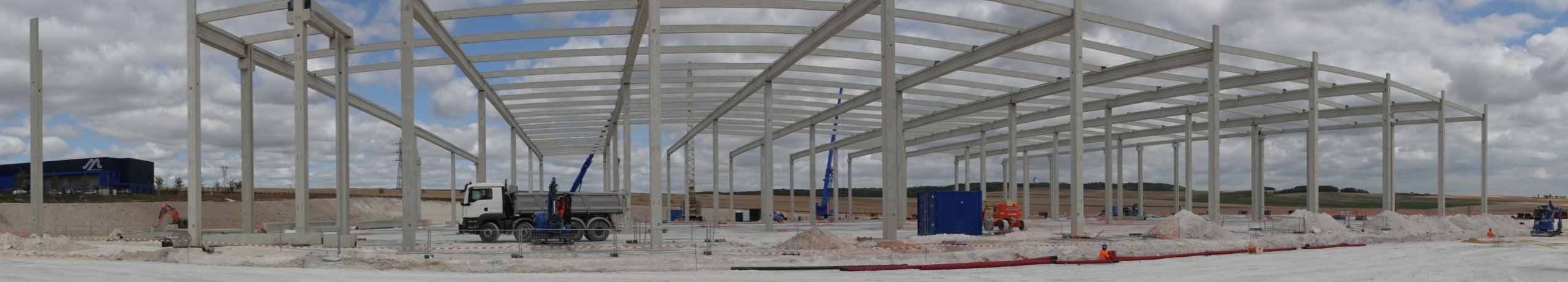
The site photo shows the column installed exactly as per the COF & ARM drawings. The crane is in the process of erecting the main beam onto the precast column system.
Once completed, the beam code list was cross-checked with the column system to ensure full consistency and coordination across the structural frame.
3.2. Beam Detail Drawings (COF & ARM)
With the coding system established, each type of beam was developed into detailed COF and ARM drawings. The process included:
-
3D Modeling: All beam types were modeled in full detail, including cross-section, span, slope, embedment holes, and starter bars for connections.
-
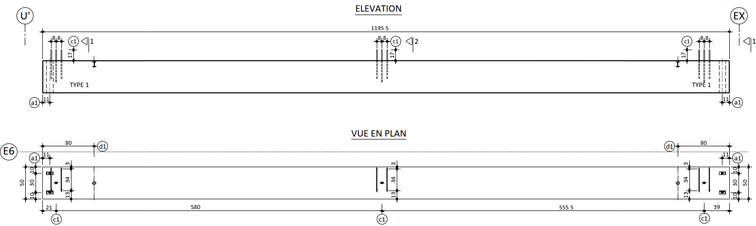
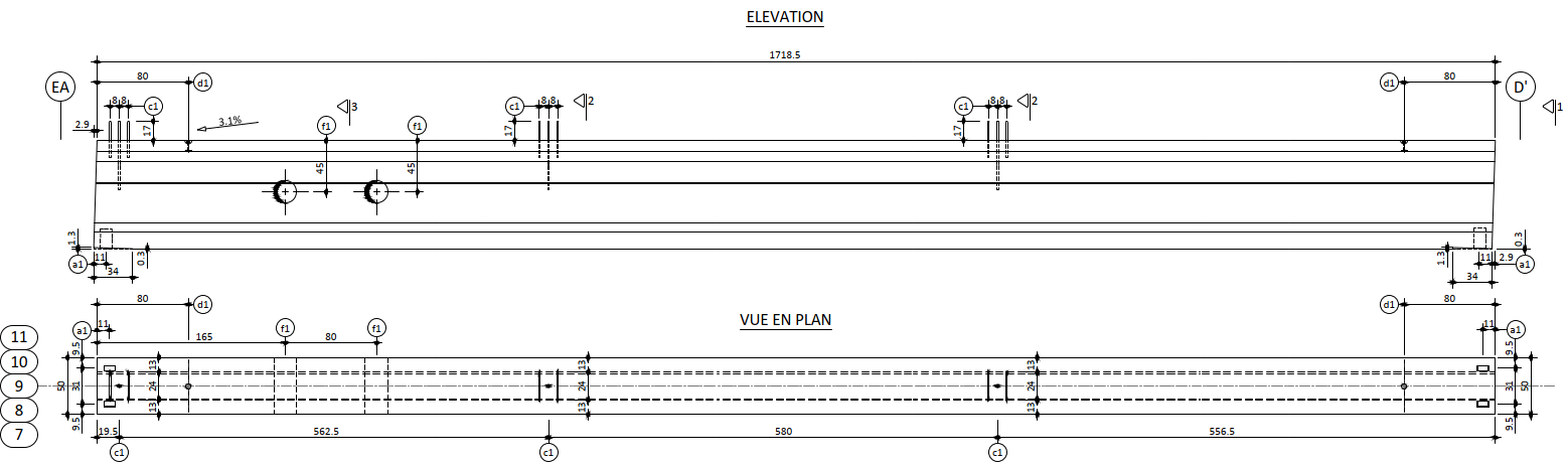
Drawing Generation: From the 3D model, 2D drawings were extracted for construction purposes, including COF drawings (showing the beam shape, dimensions, and bearing positions) and ARM drawings (illustrating longitudinal rebar layout, stirrups, reinforcement at bearing zones, and starter bars).
-
Grouping and Finalization: Drawings were grouped into main beams and secondary beams for easier management. Main beams typically have longer spans and more complex structural requirements. All notes and annotations were reviewed and finalized in AutoCAD.
-
-
Edge Main Beam (R)
-
-
Interior Main Beam (IC)
-

-
Secondary Beam (TR)
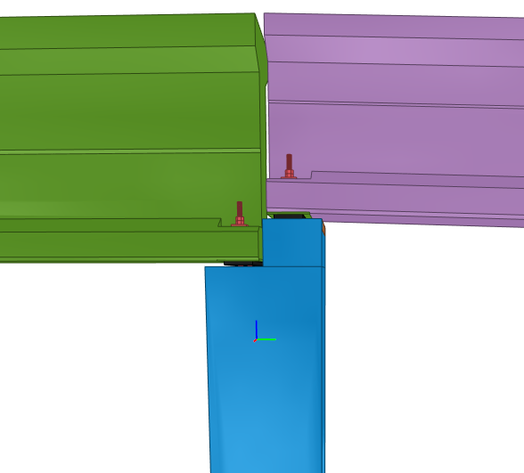
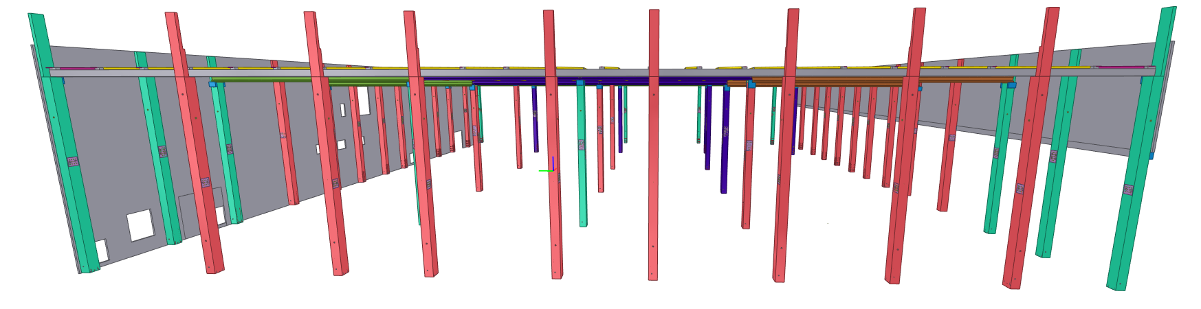
The 3D model illustrates the detailed configuration of main and secondary beams in the roof structure. Each beam is clearly coded, showing the correct cross-section, slope, and connection points. This modeling stage is essential before generating the COF and ARM drawings.
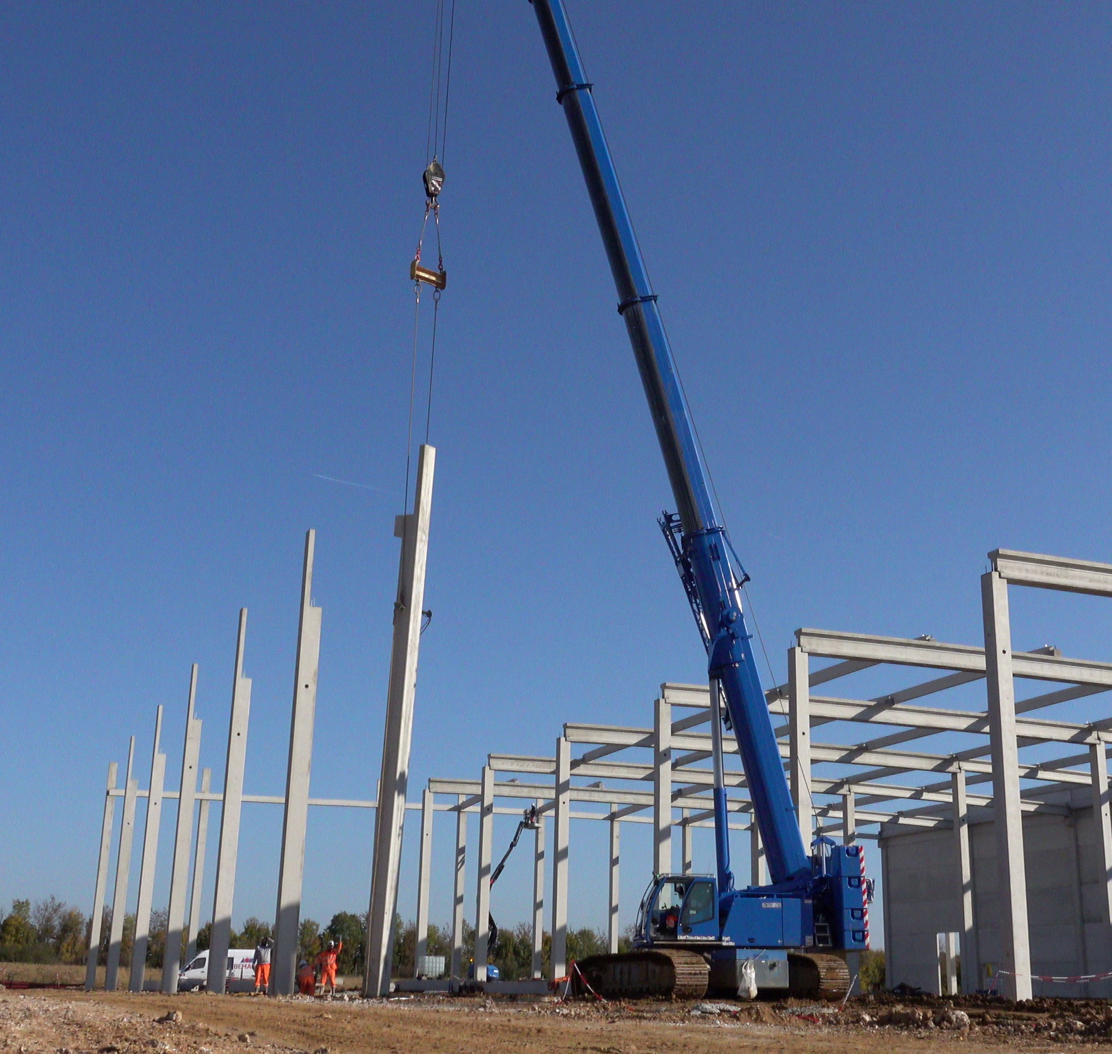
The site photo shows the construction outcome following BIM-based implementation. Beams have been installed in the correct positions, demonstrating full alignment between design drawings and on-site execution.
These beam codes can also be used to attach identification labels or QR codes to each component during production, enabling fast information retrieval on site and illustrating the connection between design and execution. The result is a complete, coordinated set of beam shop drawings, ready for production and erection.
Chapter 4: Design Implementation of Precast Concrete Walls
4.1. Wall Elevation Layout and Panel Division
The design implementation of precast concrete walls started from the wall elevation layout drawing. The first step was to remove non-structural elements (finishes, decorations) to focus on the core shape and dimensions of the wall.
The most critical step was dividing large wall segments into smaller panels to facilitate manufacturing, transportation, and installation. This division was based on technical criteria such as crane lifting capacity, transportation size limits, and location of openings. Joints between panels were also carefully designed and arranged to ensure both aesthetics and structural load transfer.
Finally, a separate layer for the wall system was created, and each panel was numbered. The numbering system typically reflected wall thickness and position (e.g., W150-1 for a 150 mm thick wall, or EW-1 for Exterior Wall). This helped categorize and manage panels with differing reinforcement and technical requirements (e.g., waterproofing, insulation for exterior walls).
-
-
-
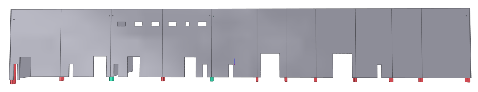
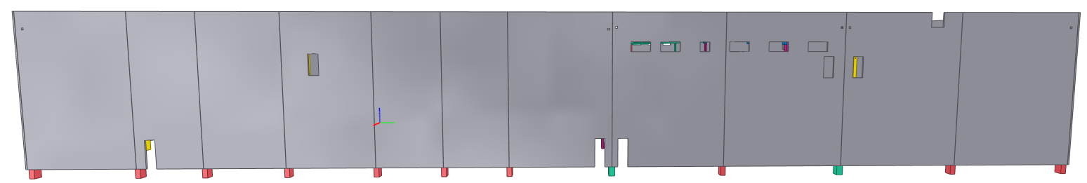
Wall Elevation Layout Drawing
-

This step required practical experience to balance between structural demands (panels strong enough, proper joint placement) and construction feasibility (panels not overly large or heavy). Thanks to experience from various industrial precast concrete projects, Pontech was able to propose an optimized panel division approach.
4.2. Wall Detail Drawings (COF & ARM)
Based on the panel division layout, COF and ARM drawings were created for each wall panel.
-
COF drawings: Clearly specify the panel’s dimensions (length, width, thickness), positions and sizes of openings. These drawings also mark all embedments such as connection plates, lifting hooks, and embedded bolts required for erection.
-
ARM drawings: Detail the reinforcement mesh (usually one or two layers), additional rebars around panel edges and openings for crack control. A rebar schedule is also attached.
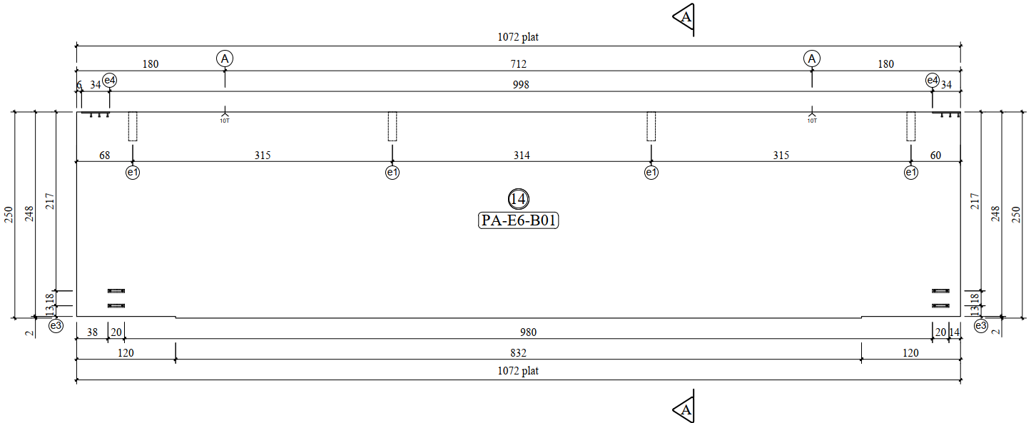
2D COF Drawing – Wall Panel
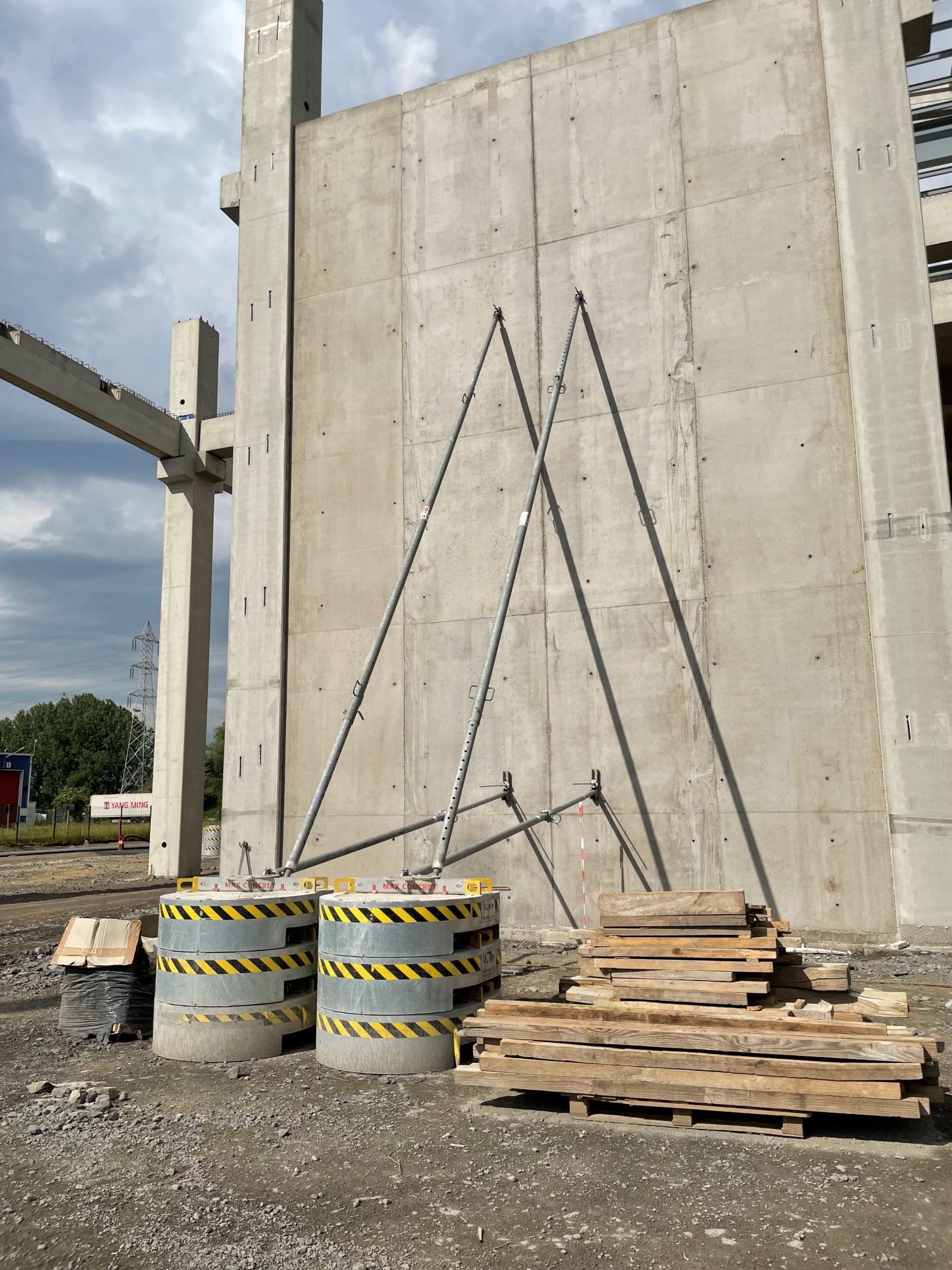
Since precast walls require extremely high accuracy for tight-fitting assembly, all drawings explicitly define acceptable tolerances (e.g., dimensional tolerance ±5 mm). Connection details between wall panels and with the structural frame are clearly shown to ensure that erection teams can assemble the panels properly and anchor them to the main structure.
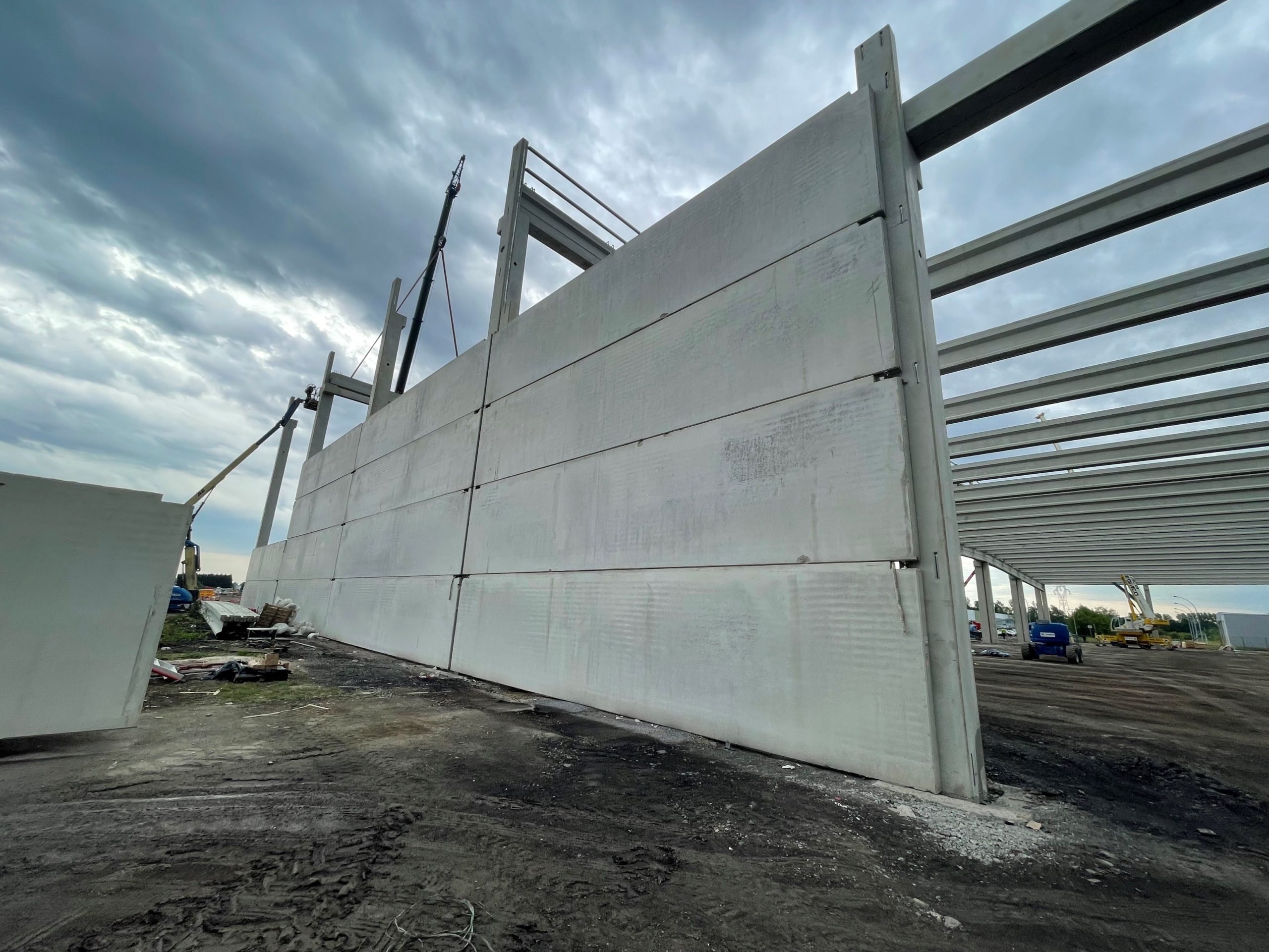
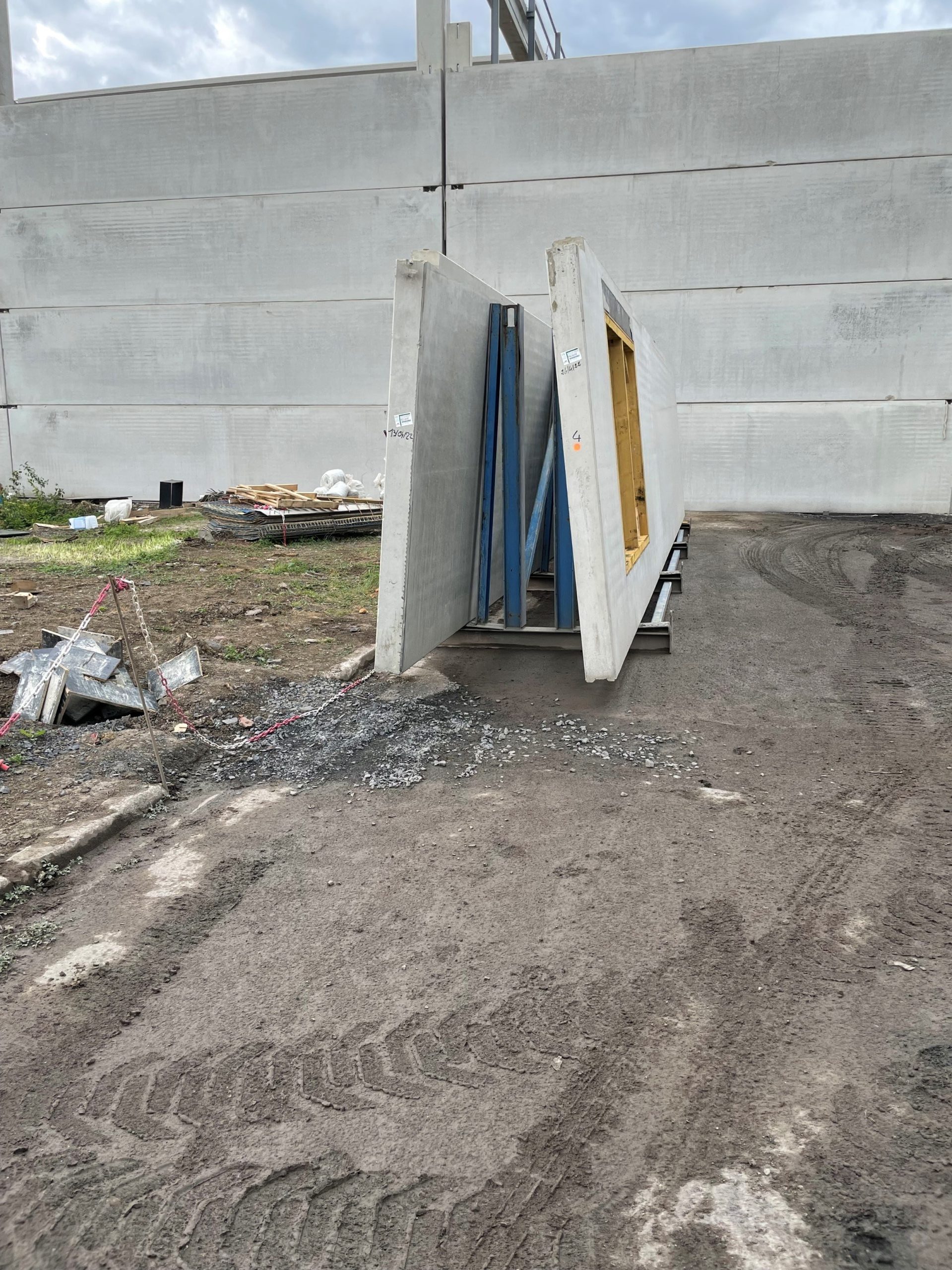
Erection of precast concrete wall panels at the construction site. The use of precast panels shortens construction time and ensures high-quality surface finishes.
Chapter 5: Connection Details
In precast concrete structures, connection details are critical for ensuring the integrated performance of the entire frame system.
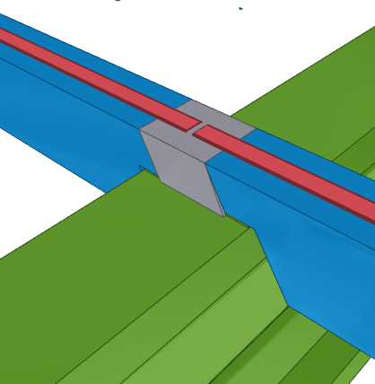
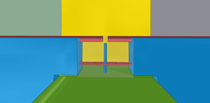
5.1. Main Beam – Secondary Beam Connection (Starter Rebar – Clavetage)
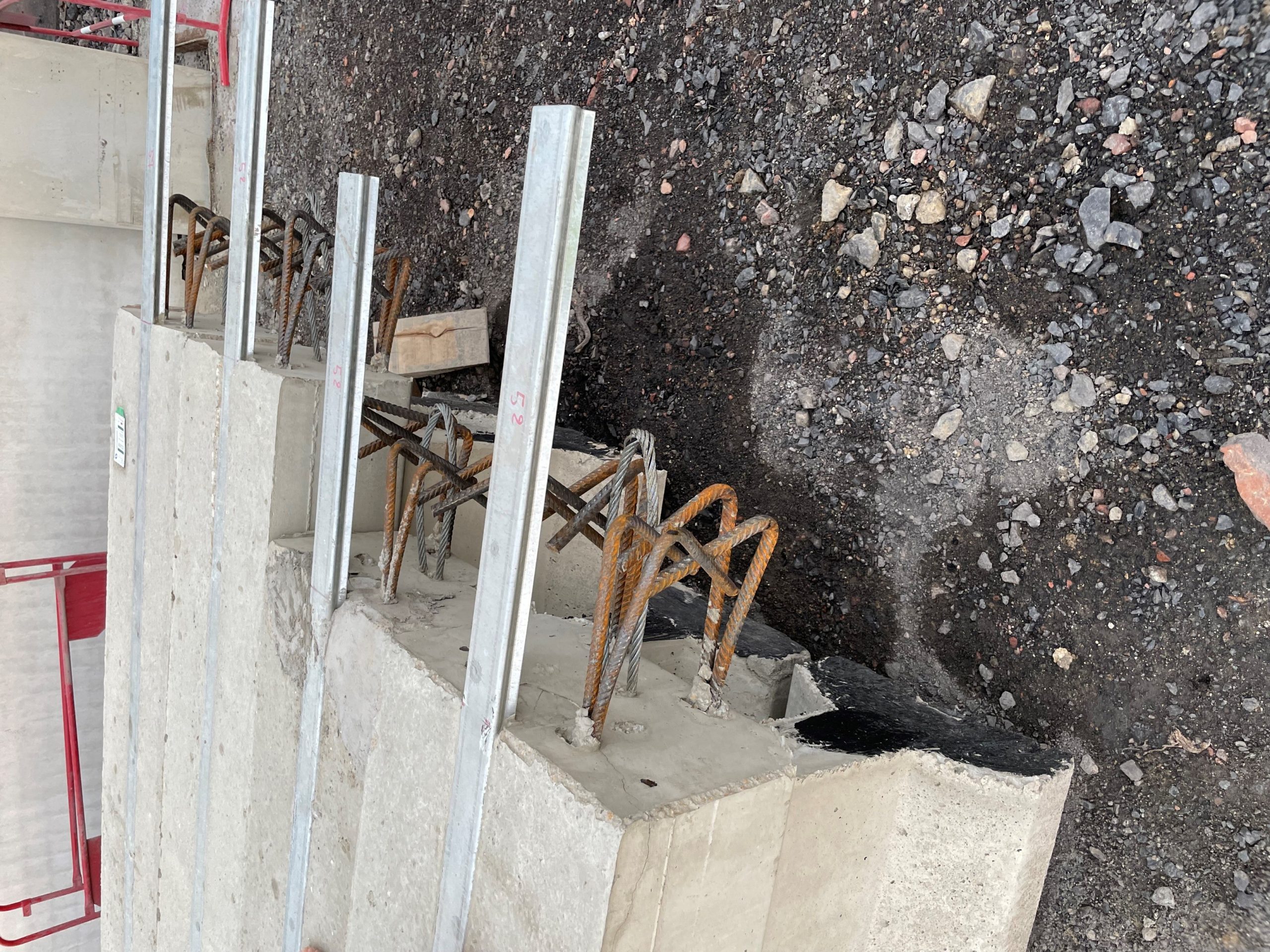
The connection between main and secondary beams in the project was executed using the CLAVETAGE method – a type of concrete “key joint.” Main beams were precast with notches or recesses, and secondary beams had starter rebars protruding from their ends. During erection, starter bars from the secondary beam were inserted into the recess and interlocked with the starter bars from the main beam. High-strength grout was then poured to complete the joint.
The detailed drawings show the number, length, elevation of starter bars, grout material (e.g., non-shrink 50 MPa), and construction instructions: beam placement, shim plate leveling, temporary fixing, then grout pouring. This design ensures the connection can handle forces, moments, and deflection as per standards.
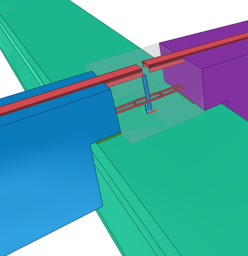
5.2. Column – Beam Connection (Neoprene Bearings and Shim Plates)
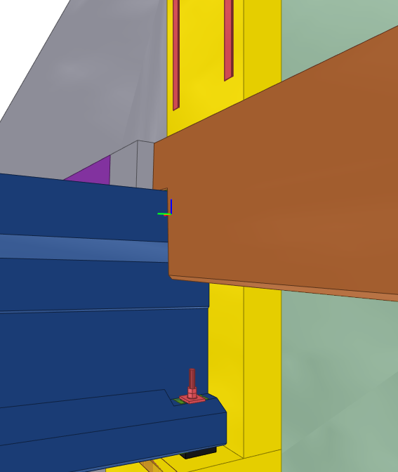
The second key connection in the precast structural system is between main beams and columns. Precast concrete beams typically rest on top of columns or consoles, using Neoprene rubber bearings to transfer loads smoothly and reduce stress concentration. Pontech drawings specify the size, placement, material stiffness (e.g., 70 Shore A), and number of bearing pads. In addition, shim plates are used to fine-tune elevation levels. If anchor bolts are used, the drawings show the embedded holes, bolt dimensions, and bolt elevations.
Thanks to these detailed drawings, beam installation onto columns is executed smoothly: construction crews know exactly how many Neoprene pads to place, how many shim plates are needed for elevation adjustment, and how to tighten anchor bolts properly. Neoprene bearings function as shock absorbers and allow small adjustments, ensuring smooth load transfer from beam to column (avoiding hard impact) and preventing local concrete cracking.
In addition to these two connections, Pontech also reviewed other project-specific details such as wall-to-column/beam connections (via dowel bars or embedded plates), and wall-to-foundation anchorage, etc. All were designed based on key principles: structural performance, construction feasibility, and design standard compliance. Each critical connection came with detailed drawings and clear installation instructions.
Chapter 6: Conclusion
By completing the detailed design for columns, beams, walls, and connections, Pontech successfully delivered a high-quality technical documentation package for the precast concrete structural solution. The professional workflow—from digital structural modeling, component coding, to the generation of COF/ARM drawings—ensured that every precast concrete element was precisely defined and well-coordinated within the overall structure.
This approach not only facilitated efficient production and installation at the factory and construction site but also significantly reduced the risk of errors, saving both time and cost.
For those interested, more projects and in-depth analyses can be found on Pontech’s official website, or feel free to contact Pontech directly for consultation on structural solutions.