What are railway structural design standards? This is a question of great interest to many investors and infrastructure developers at the outset of a railway project. Before diving into specific standards for bridges, tunnels, stations, or auxiliary facilities, let’s first review the distinctive characteristics of the railway structures to understand the role and necessity of design standards in practice.
1. General Characteristics of Railway Structures
A railway system is a distinctive structural assembly that requires a high degree of synchronization between line infrastructure (subgrade, rails, bridges, tunnels, stations) and auxiliary structures (depot, OCC, traction power substations, pedestrian bridges, longitudinal drainage, …). A modern railway system includes:
- Railway bridges
- Railway tunnels
- At-grade railway
- Stations
- Auxiliary structures
Each of the above components carries different requirements for loading, vibration, fatigue, and safety regarding operational functions; therefore, the set of applicable standards must combine appropriate design codes to cover every aspect of the works. At the design practice in Vietnam, selecting and applying suitable railway structural design standards – from TCVN/QCVN (Vietnam) to international codes such as AREMA (USA), DSRSC (Japan), or Eurocode (Europe) – is decisive for quality and service life. Technical factors such as design loads, allowable deflections, or vibration control are strictly specified in these standards.
The following sections offer a general picture of the types of railway structures a project may include – please read on.
1.1. Railway Bridges
Railway bridges are among the key structural items and are common in urban rail systems (MRT, LRT), high-speed rail (HSR), or alignments crossing complex terrain. Railway bridge structural design requires special attention to dynamic load capacity, vibration, fatigue, and long-term stability. Key requirements include control of deflection/acceleration, lateral–longitudinal displacements, rail–structure interaction (RSI), bridge–approach transition details, and deck drainage. Target service life is ≥100 years, with maintenance strategies based on data (BIM/SHM). Railway bridges can be classified by span, terrain, design loads, and structural solutions. Common solutions include:
- Prestressed reinforced concrete bridges: Typical cross-sections include box girders, I-girders, U-girders… applicable from short to long spans, high durability, reduced vibration.

Vertical section of a prestressed reinforced concrete railway bridge.
.")
Prestressed reinforced concrete railway bridge for the Etihad Railway (UAE).
For the Etihad Railway – Stage 2D, Pontech delivered end-to-end design from concept to detailed engineering within a short timeframe to meet an accelerated schedule. You can read more about the Etihad Railway – 2D project here!
- Continuous steel girder bridges: Typically steel girders with composite decks, used for medium spans 50 m ~ 70 m, suited to fast construction and quality control.

Continuous steel girder railway bridge.
- Steel truss bridges: Commonly Warren-type trusses, often used for spans 90 m ~ 120 m.

Continuous steel truss railway bridge.
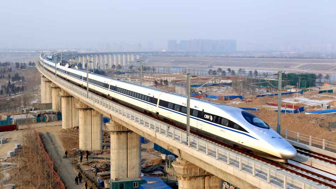
- Arch or cable-stayed bridges: Applied to high-speed rail lines or iconic structures requiring long spans along the route.

Xiangjiang Railway Cable-Stayed Bridge in China.
 of a steel arch bridge.")
Technical drawing (elevation) of a steel arch bridge.
- Extradosed bridges: An optimal choice for metro lines crossing canals or rivers in urban contexts, combining structural efficiency, low pier heights, and architectural integration.
Ho Chi Minh City Metro Line 1 is a representative example of this bridge type in Vietnam, designed under coordinated railway structural standards. Please see the project here!

Extradosed bridge on Ho Chi Minh City Urban Railway Line 1.
Key technical requirements in railway bridge design:
The structural design of railway bridges requires strict compliance with technical standards due to the specific nature of loads and operations. Below are the key requirements that must be ensured:
- Withstanding large train live loads: Large live loads – including significant traction and braking forces – govern structural solutions for each individual railway bridge. In addition, RSI affects the arrangement of consecutive spans and substructure solutions. These are prerequisite factors to achieve an optimal design for railway bridges.
- Control of vibration and displacements: Bridges must avoid resonant response under train operation for safety and riding comfort – especially on high-speed lines – and limit horizontal/longitudinal displacements to maintain high track accuracy.
- High durability and long service life: Railway bridges are typically designed for ≥100 years, accounting for repeated loading, corrosive environments, and material fatigue under Vietnam’s climatic conditions.
- Fast, safe construction with minimal urban impact: Prioritize precast girders and erection by crane or launching gantry, enabling night work or construction in constrained environments.
Urban aesthetics: Beyond engineering performance, urban railway bridges must ensure pleasing appearance – with slender components, noise mitigation, integrated lighting, and harmony with the cityscape.
1.2. Railway Tunnels
Railway tunnels are specialized structural components, typically used in underground metro alignments or complex terrain to ensure continuous operations, safety, and minimal impact on urban surfaces.
Classifications by construction method:
- Cut-and-Cover tunnels: Constructed from the surface down, build the tunnel structure, then backfill. Suitable for shallow depths, wide work zones, and straightforward construction.
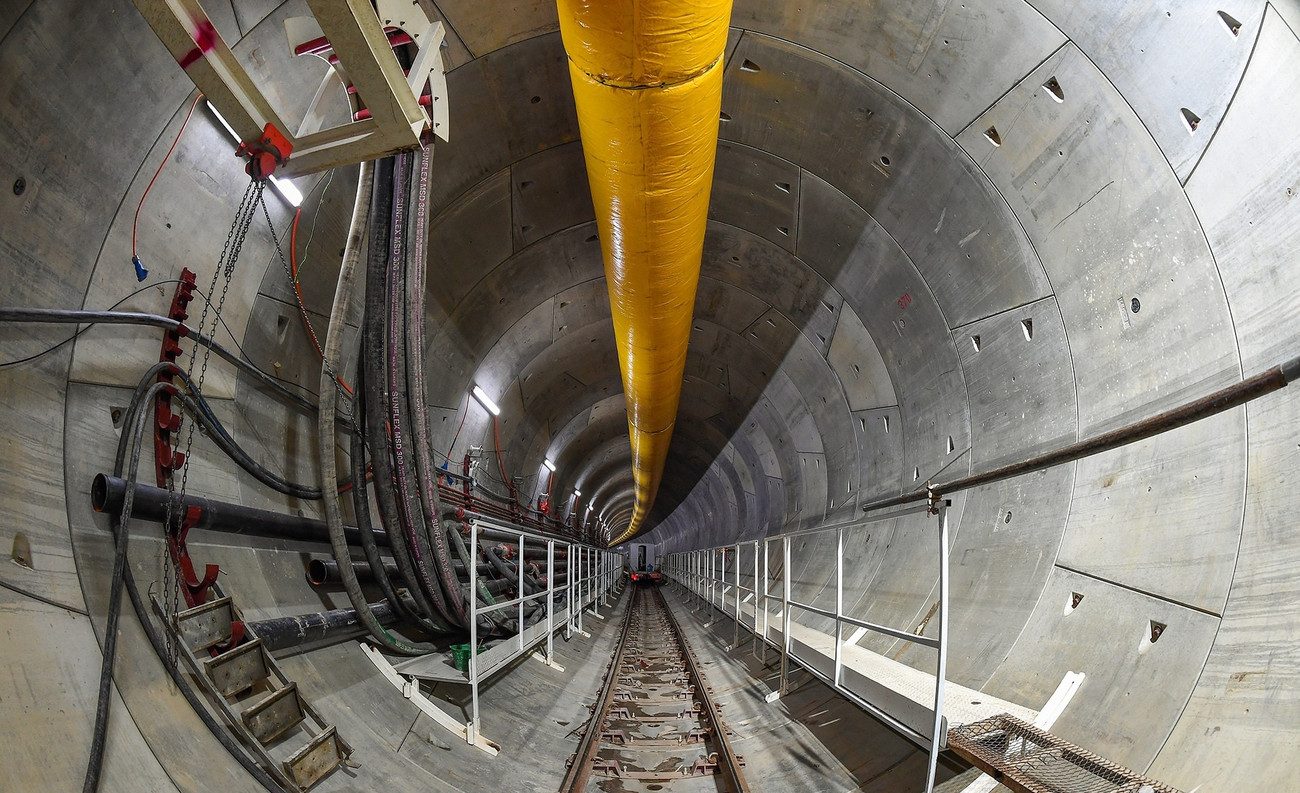
- TBM tunnels (Tunnel Boring Machine): Built with specialized TBMs, typically for deep, long tunnels through dense urban areas.
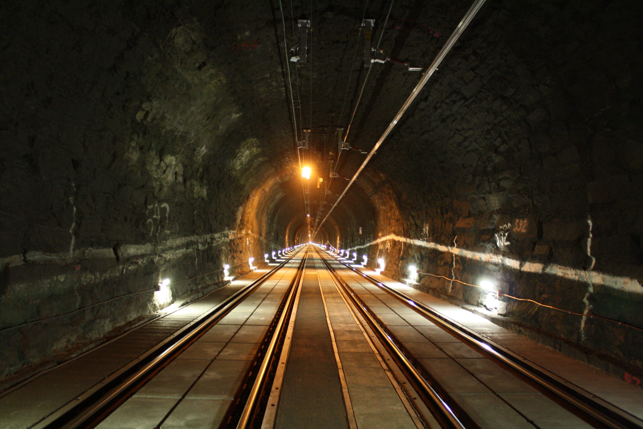
- NATM tunnels (New Austrian Tunneling Method): Executed in segments harnessing natural ground stability, flexible for mountainous terrain or complex geology.
-
-
The tunnel section of Metro Line 3 (Nhon – Ha Noi Railway Station) is constructed using a TBM.
-
-
The Arlberg Tunnel on the Trans-Alpine Railway (Austria) is constructed using the NATM method.
Main technical requirements for tunnel design:
Tunnel design requires ensuring structural integrity, operational safety, and underground environmental conditions at the same time. Below are the main technical requirements:
- Resistance to earth and groundwater pressures: Tunnel structures must remain stable under lateral earth pressure, groundwater loads, and dynamic loads from trains.
- Waterproofing and structural protection: Apply tunnel linings, drainage systems, and protective coatings to prevent leakage, corrosion, or damage to members.
- Fire safety and evacuation: Tunnels must provide periodic egress routes, mechanical ventilation, emergency lighting, and fire protection systems compliant with NFPA 130.
- Aerodynamic and air-pressure control: Train movement in tunnels causes pressure transients that affect passengers and structures; design must manage pressure and airflow effectively.
Operability and maintainability: Provide adequate maintenance access, allocate space for technical systems (power, HVAC, signaling…), and ensure workable corridors and technical walkways.
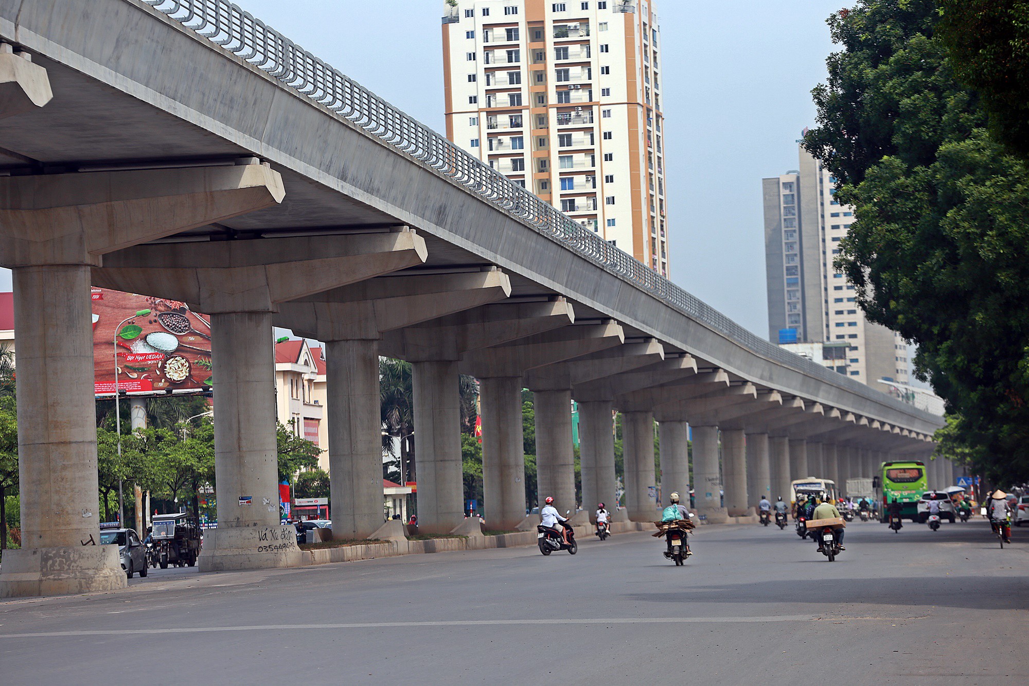
1.3. At-Grade Railway
Although metros often run elevated or underground, at-grade sections are still used in suburban areas with few crossings.
Principal technical components:
- Railway subgrade: The infrastructure directly supporting the track superstructure (rail-sleeper-ballast or ballastless slab track), transferring loads to the natural subgrade while ensuring alignment geometry, stability, and drainage.
- Track superstructure: Rails, sleepers, ballast, or ballastless concrete slab – the system that directly receives train loads and transfers them to the subgrade.
- Longitudinal drainage systems: Prevent ponding or erosion that weakens the subgrade.

At-Grade Railway.
At-grade railways are common for intercity, suburban, or flat terrain lines. While they may not demand structures as complex as tunnels or bridges, they still require strict engineering to ensure operational safety and service life.
- Subgrade and track stability: Ensure the subgrade has sufficient bearing capacity, rapid drainage, and no differential settlement. Ballast layers (if used) or ballastless systems must be designed for the intended speeds and loads.
- Dynamic load and vibration resistance: Under repeated train loads, the subgrade and track must absorb shocks and limit vibration transmission to adjacent infrastructure.
- Drainage and geotechnical control: Design longitudinal drainage to avoid flooding or landslides, especially on weak soils or during extended rainy seasons. Perform detailed geotechnical investigation prior to design.
- Continuity and alignment accuracy: At-grade railways require high accuracy in vertical and horizontal alignment to maintain stable, high-speed operations.
- Safe crossings: Provide grade separations (over/underpasses) or protected level crossings to ensure absolute safety for people and vehicles.
1.4. Stations and Auxiliary Structures
Stations and auxiliary facilities (depots, operation control centers, traction power substations, etc.) are inseparable parts of the railway system – linking passengers, rolling stock, and operations. Their design must ensure not only function but also technical integration, architectural quality, and operational efficiency.
1.4.1. Station types by position and role on the line
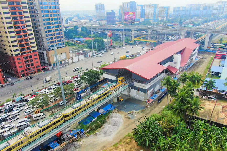
- Terminal station: Train turnaround point, often integrated with a depot or OCC.
- Intermediate station: Passenger boarding/alighting along the line.
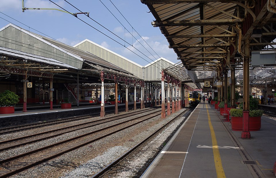
- Interchange station: Transfer between multiple rail lines or modes.
-
-
Dr. Santos Station – Southern terminal station of the LRT-1 Light Rail Line in Manila
-
-
Crewe Station – Interchange station on the West Coast Main Line (United Kingdom).
-
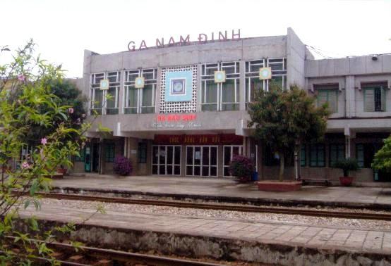
-
Nam Dinh Station – Intermediate station on the North–South line (Vietnam).
In the Manila LRT-1 Cavite Extension project, Pontech contributed structural concept development and independent technical review during detailed design, ensuring integrity and efficiency for five stations in accordance with station structural design standards.
Stations can also be classified by structural form: underground, elevated, and at-grade.
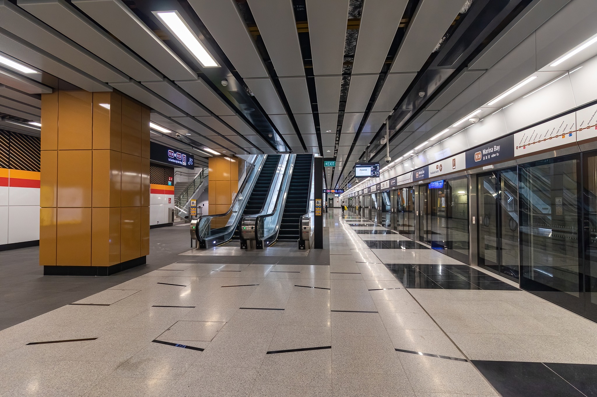
An underground station may be:
- Terminal station: e.g., Bến Thành Station – underground, terminal & future interchange.
- Intermediate station: e.g., Municipal Theatre Station – underground intermediate on Metro Line 1.
- Interchange station: e.g., Châtelet–Les Halles (Paris) – underground interchange for multiple lines.
Pontech also served as a sub-designer to the Lead Designer during the bid-design stage of NEOM – The Spine, responsible for structural design of two underground railway stations.
Main technical requirements for station design:
- Load-bearing capacity and rational spatial layout: Floors, roofs, and columns must support passenger loads, MEP equipment, and superstructures (if any). Layouts must separate flows: passengers – operations – technical zones.
- MEP & signaling integration: Provide space and provisions for HVAC, ventilation, fire protection, CCTV, lighting, lifts & escalators per international standards.
- Fire safety and evacuation: Particularly critical for underground stations, requiring proper egress paths and detection–alarm–suppression systems per NFPA 130 and equivalent standards.
- Accessibility and operations: Inclusive access for people with disabilities, clear wayfinding, and user-friendly operation.
- Aesthetics and urban identity: Stations serve as architectural landmarks; design should harmonize with surroundings and may incorporate local cultural identity – especially in major cities.
Beyond major railway structures such as bridges, tunnels, stations, and at-grade lines, modern railways include numerous auxiliary works ensuring continuous, safe, convenient, and efficient operations. These items complete the railway ecosystem, supporting technical systems, maintenance, and passenger access.
1.4.2. Common auxiliary works:
- Depots (maintenance & stabling): Facilities for maintenance, repair, cleaning, and stabling of rolling stock off-service. Include multiple sidings, technical workshops, equipment storage, and operations offices.
- OCC – Operation Control Center: Centralized control of signals, traction power, SCADA, and communications. High technical and cybersecurity requirements; 24/7 operations.
- Traction power substations (TPSS) and power systems: Provide power for the whole system; integrate switchgear, control, and energy monitoring. Design per railway electrical safety standards.
- Lineside technical/signal equipment rooms: House signaling, communications, SCADA, and level-crossing controls or signals at junctions.
- Pedestrian bridges: Connect stations to surrounding areas (car parks, malls, sidewalks…), or span the tracks to guarantee pedestrian safety. Integrate lifts, escalators, and canopies, meeting accessibility standards and fitting urban architecture.
In HCMC Urban Railway Line 1 (Ben Thanh – Suoi Tien), Pontech supported the main contractor with full detailed design (foundations, substructure, superstructure) for nine pedestrian bridges. Please see the project here!
- Maintenance walkways / service corridors: For inspection and servicing of the railway or MEP systems (power – mechanical – signaling), arranged close to the line without affecting passenger operations.
- Emergency or technical stopping areas: Strategically located to allow rapid technical access for emergencies or train incidents.
Auxiliary structures such as depots, OCC, TPSS, pedestrian bridges, and signal rooms must be synchronized with major structures to ensure safe operations and optimized lifecycle costs.
-
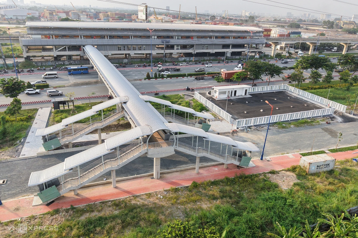
-
Pedestrian Bridge – Ho Chi Minh City Metro Line 1 Urban Railway Project.
-
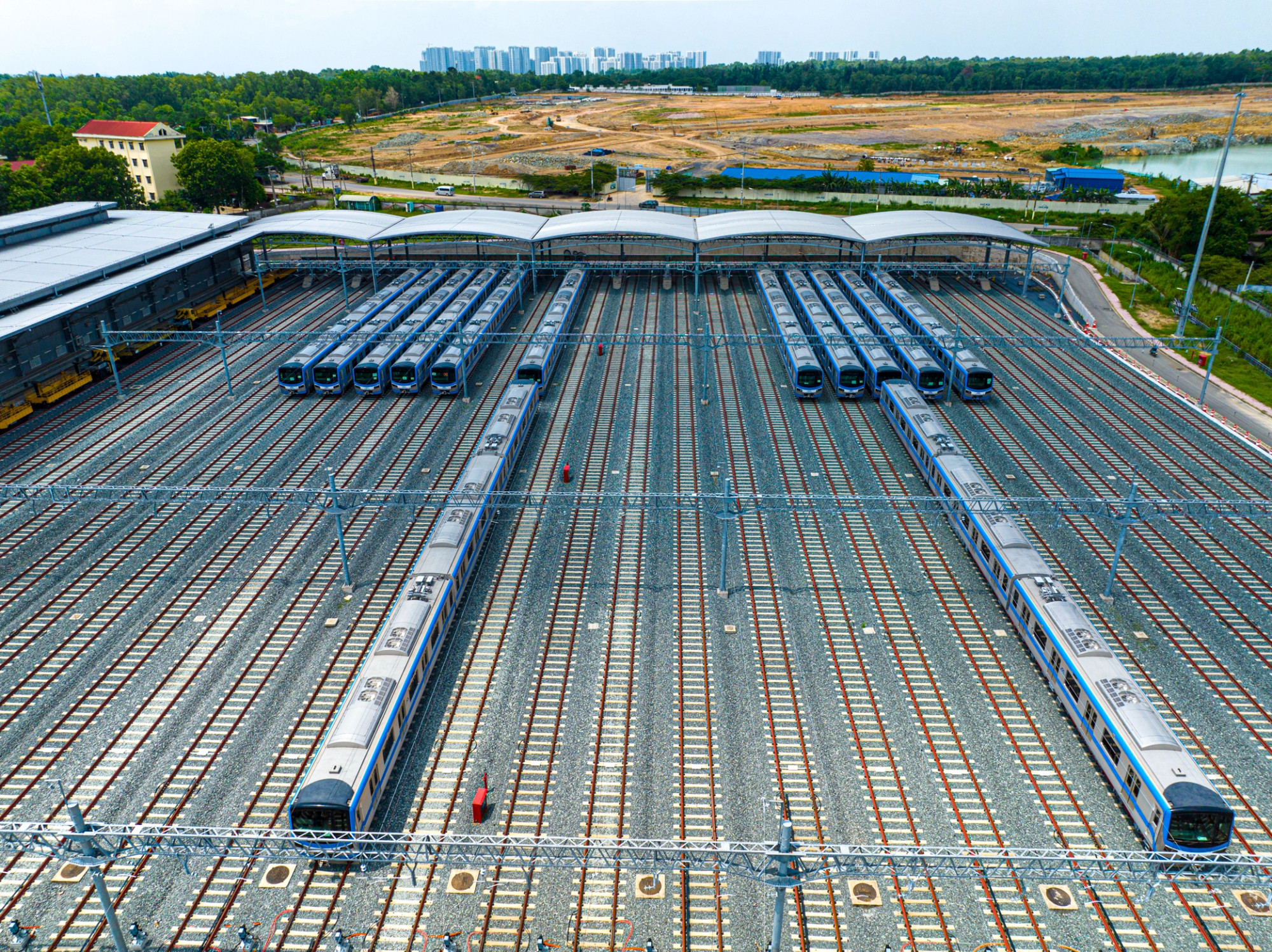
-
Long Binh Depot – Ho Chi Minh City Metro Line 1.
Technical requirements include:
- Withstanding specialized loads from MEP equipment and maintenance vehicles;
- Compliance with fire codes (NFPA 130, TCVN);
- Integration of MEP, signaling, and control systems (SCADA, ventilation, lighting, utility corridors);
- Passenger comfort, safety, and accessibility, especially at pedestrian bridges and public areas;
- Durable, maintainable materials ensuring long service life in urban operating conditions.
2. Railway Design Standards in Vietnam and Internationally
Each railway project comprises multiple types of railway structures with distinct functional and technical criteria. Therefore, combining different standard systems to meet all design criteria is essential.
2.1. Railway Structural Design Standards
Below is a comparative table by structure type for reference, including Vietnamese standards, international standards (EN/UIC/NFPA/IEC), and US equivalents – plus application guidance for Vietnam.
| Structure / Topic |
TCVN/QCVN (nearest) |
EN/UIC/NFPA/IEC (international coordination) |
US Equivalent Standards |
Suggested Application in Vietnam |
| Loads & Basis of Design (all works) |
TCVN 2737:2023 – Loads & actions |
EN 1990; EN 1991-1-x; EN 1991-2 (traffic loads on bridges) |
ASCE 7; AREMA; AASHTO LRFD (bridge combinations) |
Use TCVN 2737 as framework; for bridges adopt EN 1991-2 or AREMA. |
| Concrete structures (buildings/bridges) |
TCVN 5574:2018, TCVN 11823-2017 |
EN 1992-x |
ACI 318; AASHTO LRFD (concrete bridges); AREMA (rail concrete) |
Bridges: EN 1992-2 / AASHTO LRFD / AREMA; stations/buildings: ACI 318 / EN 1992-1. |
| Steel structures (buildings/bridges) |
TCVN 5575:2012, TCVN 11823-2017 |
EN 1993-x |
AISC 360; AASHTO LRFD |
Steel bridges: AREMA/AASHTO; station frames: AISC 360. |
| Seismic (buildings/bridges) |
TCVN 9386:2012 (EC8) |
EN 1998-1 (buildings); EN 1998-2 (bridges) |
ASCE 7 (seismic); ASCE 41; AASHTO LRFD Seismic |
Determine seismic zone; choose EC8 or ASCE 7. |
| Bridges/Viaducts – Train loads & RSI |
TCVN 2737:2023 + TCVN 11823-2017 + specific railway bridge reqs |
EN 1991-2; EN 1990 A2; UIC 774-3; EN 1992-2/1993-2/1994-2 |
AREMA Manual (train loads, CWR/RSI); AASHTO LRFD |
Check vibration & RSI for bridges with CWR. |
| Railway tunnels |
QCVN 06:2022/BXD (fire protection); EC2/EC7 for structure |
NFPA 130; UIC 779-11; BS 6164 (construction safety); EC2/EC7 |
NFPA 130; ASCE/USACE; ACI 318/350 (as applicable) |
TVS/egress per NFPA 130; tunnel sections per UIC 779-11. |
| At-grade & Trackform |
TCVN 13937-1/-2:2024 (slab track); TCVN 13566-x; 13695-x; 13858-1:2023 |
EN 13481/13146 (fastenings); EN 13848 (track geometry) |
AREMA (Track); ASTM C136/D75 (materials testing) |
Control geometry/vibration; tolerances for slab track. |
| Stations & auxiliary works |
QCVN 06:2022; QCVN 10:2014/2024 |
NFPA 130; NFPA 101; EN 50121 (EMC) |
NFPA 130; NFPA 101; IBC; ADA; IEEE/NEC |
Fire & egress: NFPA 130 + QCVN 06; accessibility: QCVN 10 / ADA. |
| Pedestrian bridges |
TCVN 5574/5575; QCVN 10:2014/2024 |
EN 1991-1-1/-1-4; EN 1993/1992 |
AASHTO Guide for Pedestrian Bridges; ASCE 7; AISC 360 |
Control comfort vibration, crowd loads & wind. |
| Traction power / OCS – TPSS |
(Per Vietnamese electrical regulations in project) |
EN 50119; EN 50121-x; IEC 60850; EN 50126/8/9 |
IEEE 80; IEEE 1653.x; NFPA 70 (NEC); IEEE 519 |
Coordinate OCS mast foundations, grounding & EMC with civil works. |
| Embankments & geotechnics |
TCVN 9362/9363; TCVN 10304:2014 |
EN 1997-1; UIC 719R/IRS |
AASHTO LRFD; FHWA GEC |
Global stability, settlements; subgrade layers per UIC/AASHTO. |
Notes: Urban metro, HSR, or LRT projects in Vietnam commonly combine TCVN with international standards depending on technical requirements and funding.
2.2. Why Do We Need to Combine Multiple Railway Structural Design Standards?
In railway design and construction, combining multiple technical standard systems – TCVN, Eurocode, AASHTO / ACI / AREMA, NFPA – is not only a trend but also a necessity to ensure technical, legal, and economic effectiveness throughout the project lifecycle. This arises from two main factors: the technical specificity of each structure and the realities of implementation in countries developing their rail sectors.
Each structure type has its own technical characteristics:
A railway line is not just rails; it comprises a set of railway structures: bridges, tunnels, at-grade sections, stations, depots, technical buildings, pedestrian bridges… Each has specific technical requirements, design loads, and operating environments, requiring standards appropriate to function and use conditions.
Examples:
- Bridges need robust standards in load combinations related to heavy train live loads, fatigue, vibration, and stability – such as EN 1991-2 or AREMA.
- Stations and underground works require fire safety, egress, and passenger operation standards like NFPA 130 plus specialized MEP guidelines.
- Tunnels require standards for earth pressure, groundwater, aerodynamics, and forced ventilation – combining structural and environmental/safety standards.
No single standard system can cover all technical specifics across railway structures – hence coordinated application is essential.
Coordinating standards for railway structures to match design–construction–operation capabilities:
In practice, many railway projects involve designers, consultants, and contractors from different countries or jurisdictions. Each brings familiar standards shaped by experience and practical capability.
In many countries developing rail systems:
- Domestic standards may be limited or not fully updated for specialized scenarios such as metro tunnels, automated depots, or precast components for HSR bridges.
- Construction realities depend on local supply chains, equipment, and technical proficiency, so design standards must adjust flexibly.
Therefore, combining domestic and international standards is the optimal approach.
2.3. Key Considerations in Implementing Railway Structural Design
Given the above precision requirements, when implementing the structural design of railway structures, especially on international projects, note:
- Standard coordination: Combine TCVN and international standards carefully to avoid conflicting criteria.
- Local adaptation: Interpolate/adjust foreign standards to Vietnam’s climate, geology, and construction methods.
- Technology transfer & training: Keep designers updated on standards and advanced software.
- End-to-end control (design–construction–operations): A good design only works when the entire chain is tightly controlled.
3. Construction Technology in Railway Projects
Modern railway construction requires tight coordination among structural engineering, digital technologies, and construction organization to ensure schedule, quality, and operational safety. Each of the railway structures – viaducts, tunnels, stations, or auxiliary works – uses different methods tailored to its technical specifics.
3.1. Bridges – Viaducts
Railway viaducts in metro, LRT, or HSR lines are typically designed and constructed with industrialized methods:
- Full-span precast (launching girder): High industrialization, fast schedules, enhanced quality control.
- Balanced cantilever construction: For long spans and river/canal crossings; control of camber is essential.
- MSS / ILM: High mechanization; ILM (incremental launching) works well for straight/low-curvature bridges; control friction and stability during launches.
- Steel–concrete composite: Reduces self-weight and shortens erection time; requires careful fatigue and shear connection checks.
3.2. Railway Tunnels
Depending on geology and depth, railway tunnels use one of three main methods:
- Cut-and-Cover: Economical for shallow stations/tunnels; requires robust temporary works and traffic management.
- TBM (Tunnel Boring Machine): For long urban tunnels-simultaneous excavation, lining installation, and muck removal. The process is automated and digitally controlled, ensuring high accuracy and minimal surface impact.
- NATM (New Austrian Tunneling Method): Common in hilly terrain, weak soils, or complex geology. The tunnel is built in short stages with real-time geotechnical monitoring to control stress and deformation – key to protect the works and surrounding environment.
3.3. Stations and Auxiliary Works
Stations, depots, OCC, and auxiliary works such as pedestrian bridges and traction power buildings employ flexible technologies combining structures and technical systems:
- Prefabricated steel or precast concrete: Accelerates construction, reduces weather dependency, improves quality control.
- Integrated MEP–fire systems during erection: Install mechanical, electrical, HVAC, security, CCTV, lighting, and fire protection concurrently with structure. Integration shortens completion time and reduces technical clashes.
- BIM 4D, 5D applications: Construction models integrating time (4D) and cost (5D) help owners track schedule–quantities–costs in near real-time and support future maintenance.
4. Conclusion
Mastering and flexibly applying railway structural design standards is the foundation for ensuring quality, safety, and investment efficiency across railway structures and projects – from bridges and tunnels to stations and auxiliary facilities. From technical perspectives to field implementation, design teams must continuously update and integrate standards tailored to Vietnam’s context while moving toward international best practice.
Discover more about Pontech’s high-speed railway bridge, station, and auxiliary projects, or contact us for tailored design solutions that meet international standards.
↪️ Contact Pontech here!